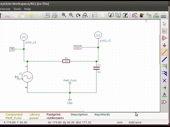
Device Model creation and Simulation - English
This is a sample video. To access the full content,
please
Login
- Questions posted on Forums
- eSim Tutorials - English
-
Code file for germanium diode 1N34A doesn't exist in esim 2.1
I can't find the code file for germanium diode 1N34A
02-03M 10-20S Karthick_1507
Answer last updated on: Jan. 3, 2025, 4:30 p.m.
-
Problem facing regarding wire connection and error produced in connection
I'm facing a problem in proper wire connection in schematic diagram. Also, how to delete the component selected on the editor window?
07-08M 30-40S priti.rajput21
Answer last updated on: Sept. 22, 2019, 6:40 p.m.
-
REGARDING MARKERS DURING SIMULATIONS
After annotation and when we run the circuit then the markers arises.. How to remove that?
01-02M 0-10S swati.vashist19@gmail.com
Answer last updated on: Sept. 22, 2019, 6:37 p.m.
-
Electrical rule check
Electrical check rules not cleared, even though all connections are perfectly connected. What can I do for this problem?
07-08M 50-60S PushpaGangwaleshim
Answer last updated on: Sept. 6, 2019, 1:06 p.m.
-
1
 Schematic Creation and Simulation
 -
2
 Simulating an Astable Multivibrator
 -
3
 Mapping Components with Footprints
 -
4
 Setting Parameters for PCB designing
 -
5
 Laying Tracks on PCB
 -
6
 PCB Layout for Astable Multivibrator
 -
7
 Creating a Device Model
 -
8
 Uploading a Spice Device Model
 -
9
 Subcircuit Builder
 -
10
 Editing a Subcircuit
 -
11
 Uploading a spice Subcircuit file
 -
12
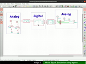
 Mixed Signal Simulation using NGHDL
 -
13
 Mixed Signal Simulation using NgVeri
 -
14
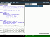 Makerchip IDE
 -
15
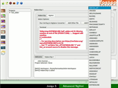 Advanced NgVeri
 -
16
 eSim interface to OpenModelica
Questions posted on ST Forums:
5108 visits
Outline:
* Create device model *Add the device model to a circuit *Add parameters of device model *Remove parameters of device model *Edit the value of a parameter *Save the device model *Add the edited device model *Compare the simulation output before and after editing the device model *Upload the external device model *Locate the uploaded device model from User Library
| Width: | 880 | Height: | 660 |
|---|---|---|---|
| Duration: | 00:07:25 | Size: | 6.9 MB |
Show video info
